Sprite Assembler Makes
Multiframe Sprites a Snap
 A common technique for generating sprite animations on the
Yaroze involves the creation of a single TIM file which
holds several frames concatenated together. Your program
uses the GsSPRITE attributes "u" and "v" to change the
in-page offset to pick out the frame it needs. For
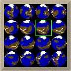
instance your 128x128 TIM might consist of a 4x4 matrix of
pictures, each one representing a 32x32 pixel frame. Then
if you want frame #7 you would point u and v to (64, 32).
See the illustration to the right.
A common technique for generating sprite animations on the
Yaroze involves the creation of a single TIM file which
holds several frames concatenated together. Your program
uses the GsSPRITE attributes "u" and "v" to change the
in-page offset to pick out the frame it needs. For
instance your 128x128 TIM might consist of a 4x4 matrix of
pictures, each one representing a 32x32 pixel frame. Then
if you want frame #7 you would point u and v to (64, 32).
See the illustration to the right.
Typically you would render the animation in a 3-D package
and save each frame as a single graphic. Then you need to
crop out any excess background, leaving only the object in
which you are interested. Next you must resize each frame
to meet your game's requirements (32x32 in the above
example). Finally you take all of these resized graphics
and concatenate them together to get your final file
containing the full animation. The Sprite Assembler
was designed to automate the copping, resizing, and
concatenation steps in that process.
The program reads any number of 8- or 4-bit BMP files,
performs each step in sequence, and outputs a final TIM
file (or a BMP file if you want to do further manipulations).
The entire program is run via command line parameters
which makes it simple to place in a batch file.
The remainder of this article details the various functions
that the Sprite Assembler performs, and how the user
can affect them.
Cropping
 The program must first crop all of the input graphics so
it's only left with the interesting part of each picture.
We will be talking about "cropping rectangles" quite a bit
so we first need to tell you what this means to the program.
Quite simply it is the largest region in the graphic which
only includes sprite information; all empty rows and columns
around the border are eliminated. This is represented as a
pair of coordinates which indicate the upper-left and
lower-right corner of that rectangle.
Take a look at this figure. Assuming the bitmap's original
size is 64x64, the cropping rectangle would have an
upper-left coordinate of (11, 16) and a lower-right
coordinate of (41, 46).
The program must first crop all of the input graphics so
it's only left with the interesting part of each picture.
We will be talking about "cropping rectangles" quite a bit
so we first need to tell you what this means to the program.
Quite simply it is the largest region in the graphic which
only includes sprite information; all empty rows and columns
around the border are eliminated. This is represented as a
pair of coordinates which indicate the upper-left and
lower-right corner of that rectangle.
Take a look at this figure. Assuming the bitmap's original
size is 64x64, the cropping rectangle would have an
upper-left coordinate of (11, 16) and a lower-right
coordinate of (41, 46).
But just how does the program determine what is considered
background and what isn't? This is one of the pieces of
information you must give Sprite Assembler. You can
select one of two switches. The first tells the
program to regard any black pixel as background -- that is, a
pixel with RGB components of (0, 0, 0). The other
switch lets you specify a coordinate in your BMP. Whatever
color is at that pixel will be considered the background.
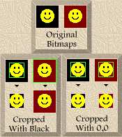 The figure to the left shows two sample BMP files and how they
are cropped using each method. Using the first method, the
first picture is cropped as we expect, but the second one is
not cropped at all because it contains no black around the
edges. With the second method, picking a coordinate of (0,0),
they are both cropped. This is because the background color is
different for both. The color at 0,0 in the first BMP is black
while in the second it is red.
The figure to the left shows two sample BMP files and how they
are cropped using each method. Using the first method, the
first picture is cropped as we expect, but the second one is
not cropped at all because it contains no black around the
edges. With the second method, picking a coordinate of (0,0),
they are both cropped. This is because the background color is
different for both. The color at 0,0 in the first BMP is black
while in the second it is red.
You can also select a threshold value which will expand the
number of background colors the program sees. If a
particular color is within that threshold of the background
color (either black or the color at the given coordinates -
see previous paragraph) it is cropped as well.
Another option you can give works with the threshold. It
tells the program to convert any color within the tolerance
to the background color. The table below shows how
these two parameters work.
 |
 |
 |
 |
 |
 |
| Original |
No Thresh |
Thresh=96 |
Thresh=96 &
Convert |
Thresh=192 |
Thresh=192 &
Convert |
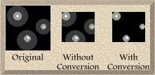 Notice the difference between when you just have a
tolerance and when you have both a tolerance and conversion
turned on. Why would you want to convert the colors?
Suppose you have the image to the right. If you use a
tolerance without converting you'll have a bunch of partial
circles on the edges (which might or might not be what you
want). With conversion on you're left with just the colors
outside the tolerance.
Notice the difference between when you just have a
tolerance and when you have both a tolerance and conversion
turned on. Why would you want to convert the colors?
Suppose you have the image to the right. If you use a
tolerance without converting you'll have a bunch of partial
circles on the edges (which might or might not be what you
want). With conversion on you're left with just the colors
outside the tolerance.
Okay, the program now knows how to crop any bitmap we give
it. But since we're going to give it several frames of
animation how do we tell it how each of these pictures are
related? There are two parameters you can specify. The
first tells the program to crop each picture individually
without regard to the other frames; each cropping rectangle
will be independent. The second makes it generate a
worst-case cropping rectangle. It reads in each BMP,
determines how to crop each one, and selects a single
cropping rectangle which will work for all frames such that
no data is lost.
The simplest switch tells Sprite Assembler to crop
each graphic on its own. It will generate a separate
cropping rectangle for each picture. This is useful when
you know your object shouldn't move or change size during
the animation. The figure at the top of this page is a good
example. Each frame of the planet animation should be the
same size.
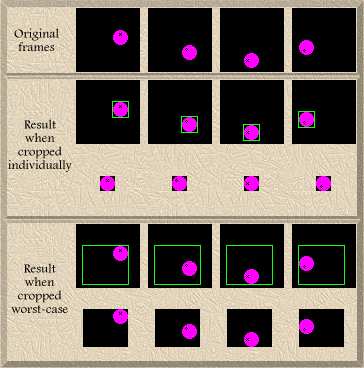 The second switch determines a worst-case cropping rectangle
and applies that to all pictures. Say we have an
animation of a ball bouncing (see figure). If we were to use
the previous parameter (which crops individually), we would end
up with just the ball; the bouncing effect would be lost.
However, by using the second method the program will figure out
the minimum cropping rectangle which fits all of the individual
pictures. It compares the X and Y coordinates of the the
corners that bound each individual cropping rectangle and
selects the worst case coordinate. That is, the coordinate
which is most to the outside of the picture. As you can see
from the figure, this switch is useful when your object moves
around and you want to keep the relative position the same.
The second switch determines a worst-case cropping rectangle
and applies that to all pictures. Say we have an
animation of a ball bouncing (see figure). If we were to use
the previous parameter (which crops individually), we would end
up with just the ball; the bouncing effect would be lost.
However, by using the second method the program will figure out
the minimum cropping rectangle which fits all of the individual
pictures. It compares the X and Y coordinates of the the
corners that bound each individual cropping rectangle and
selects the worst case coordinate. That is, the coordinate
which is most to the outside of the picture. As you can see
from the figure, this switch is useful when your object moves
around and you want to keep the relative position the same.
Resizing
 Now that Sprite Assembler knows how to crop each
picture, we have to tell it how large to make each frame.
A few parameters let you tell the program the height and
width of each frame. You can also tell it to maintain the
aspect ratio of each frame if that is important. Take a
look at the example. The original picture is 128x64. Suppose
we want to reduce this to 48x48. This will result in the
right hand graphic in the example you see.
Now that Sprite Assembler knows how to crop each
picture, we have to tell it how large to make each frame.
A few parameters let you tell the program the height and
width of each frame. You can also tell it to maintain the
aspect ratio of each frame if that is important. Take a
look at the example. The original picture is 128x64. Suppose
we want to reduce this to 48x48. This will result in the
right hand graphic in the example you see.
 However, we can tell the program to maintain the aspect
ratio of the original. There are two choices. One
parameter says that the height and width you give are the
maximum values you want and the program should decrease one
or the other to maintain the aspect ratio. In this case,
the width is the larger of the two dimensions so the it
will assign a new width of 48 and compute the new height
based on the aspect ratio of the original (24 since it's
2:1).
However, we can tell the program to maintain the aspect
ratio of the original. There are two choices. One
parameter says that the height and width you give are the
maximum values you want and the program should decrease one
or the other to maintain the aspect ratio. In this case,
the width is the larger of the two dimensions so the it
will assign a new width of 48 and compute the new height
based on the aspect ratio of the original (24 since it's
2:1).
 The second parameter does the opposite. It will take
the height and width as minimum values and increase the
appropriate dimension. So the height would be fixed at 48
and the new width would be 96 (again, to maintain the 2:1
aspect ratio).
The second parameter does the opposite. It will take
the height and width as minimum values and increase the
appropriate dimension. So the height would be fixed at 48
and the new width would be 96 (again, to maintain the 2:1
aspect ratio).
Concatenation
Okay, now we have our individual bitmaps cropped and
resized. The last step is assembling them into a single
file and writing it out as a TIM (or BMP). A parameter you
give tells the program how many pictures to put on each row
of the final graphic. So for instance if you have 16 frames
of animation and tell Sprite Assembler to put 4
frames on each row, you would end up with a picture arranged
into 4 rows of 4 columns (like the one at the top of this
page). The program will fill in any unused space with
zeroes (CLUT entry 0).
In addition to giving you one concatenated output,
Sprite Assembler can also produce all intermediate
files (as BMPs). It will save the files after three steps:
tolerance conversion, cropping, and resizing. You can take
these files and load them in a paint program to perform some
operations on them. Then you can use them as inputs to
Sprite Assembler to assemble your final TIM.
There you have it!
Your TIM file is ready to be included in
your game and you didn't have to do all that boring and
tedious cropping/resizing yourself. If you need to change
the animation slightly, no problem! Just rerender and then
rerun Sprite Assembler with the same parameters and
you'll be set. It's a tremendous time saver. Click on the
icon below to download a zip containing the program and
documentation. If you have any questions please
feel free to mail me.
sprtasm.zip (123k)

TIM Manipulator Lets You
Change a TIM from the Inside Out
Converting a picture from 8-bit color depth to 4-bit can be
a disappointing process. You are often at the whim of another
program (TIM Tool for example) to choose which 16 of the 256
colors to keep. The results are often not exactly what you
want. With the TIM Manipulator you get to make
the decisions. You can combine colors, change colors, or
consolidate colors all with a few simple commands. You can
view your progress and if you like what you see you can write
it out to a new TIM file. Even if you don't want to convert
8-bit TIMs to 4-bit TIM Manipulator still offers you
in-depth control of your TIMs.
When converting a 8-bit TIM to 4-bit, the most common
command is to replace one CLUT entry with another. You
specify a source and destination CLUT entry. Then all pixels
which reference the destination are changed so they reference
the source, effectively eliminating one color from the TIM.
The CLUT is not altered; only the
pixel values are changed. Also note that the destination
CLUT entry is no longer used in the TIM.
How do you determine which CLUT entries to eliminate?
TIM Manipulator can give you some information to help
with your decision. It only lists those colors which are
actually used. Each entry has 3 pieces of info: the CLUT
entry number, the number of pixels which reference that CLUT
entry, and the RGB+Transparency information. You can use the
number of pixels to find a candidate for replacement. For
instance, if one CLUT entry is used by only 10 pixels then
you could probably get rid of it without much impact. Simply
choose another entry which has similar RGB values and replace
it with that one.
If all of your CLUT entries are used quite often another
method is to find two entries which have very close RGB values.
Then replace one with the other and change the RGB values of
the combined entry to the average of the two. TIM
Manipulator lets you select any CLUT entry and change
its RGB and transparency to any value.
After you've gotten the number of used colors down to 16 or
less (which is required in order to save it as a 4-bit TIM),
you need to make sure these colors occupy the lowest 16 entries
in the CLUT. The consolidate command will do this
automatically for you. Your TIM will look exactly the same as
before, but each pixel will reference a CLUT entry from 0 to
15.
If you want to organize your CLUT a little better you can
use the swap command to exchange two CLUT entries. The
program will also go through the TIM and change all pixels
which reference one to instead use the other. As a result it
won't change your TIM's appearance, but your CLUT will be the
way you want it. This might be useful if you want your CLUT
ordered a certain way so you can easily change it at run time
in your game.
You can also view your progress. TIM Manipulator
will print out your TIM in 320x200 256-color mode. You can
zoom and scroll around to look at all parts of your
picture.
Make a mistake? The program saves your last action in an
undo file. A simple key press restores your previous state.
You can save your work to a TIM file at any point. You
can always save it as an 8-bit TIM. In order to save as a
4-bit TIM, though, you need to make sure your picture only
uses at most 16 CLUT entries (the bottom 16 entries
preferably).
While I use this utility for my own purposes, I would like
to make it as versatile and useful as possible. To that end I
welcome bug reports or even suggestions for improvements.
TIM Manipulator is available for download by clicking
the icon below.
timmanip.zip (42k)
Top
This web page and its contents are © 1997 Scott Cartier